|
MAXIMUM VALUES IN HAZARDOUS AREA |
|
|
10,5 V 32 mA 800 nF 5 mH |
Note .: Relay switch on by increasing the current in
the loop. |
|
|
|
 |
|
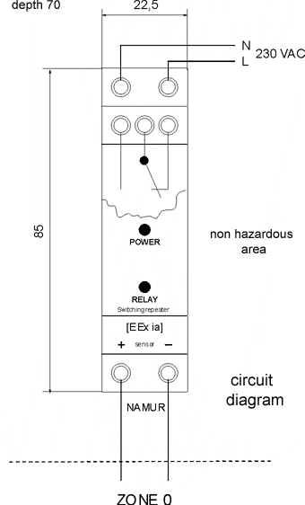
| UNIT NJ 20 FOR USE IN HAZARDOUS AREA |
CHARACTERIZATION
|
TECHNICAL PARAMETERS |
|
Supply voltage |
230 V / 50 Hz |
| Range of supply voltage | 200...250 VAC |
| Maximum power input | 1,6 VA |
| Working area | non hazardous |
| Working temperature range | -20°C to 60°C |
| Maximum rel. humidity | 95% by 20°C |
| Case protection | IP 40, terminals IP 20 |
| Output voltage using in hazardous area | 8,0 V |
| Output current using in hazardous area | < 6 mA |
| Maximum switching current | 2 A (ZONE 0) |
| Maximum switching voltage | 250 VAC |
| Maximum switching power | 100 VA (ZONE 0) |
| Maximum switching frequency | 15 Hz |
| Dimensions | 22,5mm x 85mm x 70mm |
| Material of case | NORYL SE1 (General Electric) |
| Placing | switchboard with IP 20 min. |
|
MAXIMUM VALUES IN HAZARDOUS AREA |
|
|
10,5 V 32 mA 800 nF 5 mH |
Note .: Relay switch on by increasing the current in
the loop. |
|
|
|
|
|