Recommended
connection for Converter ISO485
Direction of transmission AUTO switching mode
Converter connection for automatic switching of transmission -connected with DTE(PC)
device by connector Cannon25 or 9
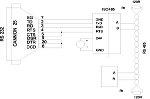
Notes for connection:
2 x GND terminals are inner connected (common ground of power supply
and RS232 at DTE(PC) side.
Terminal resistors Rt value the same as line impedance (e.g.120 Ohms)
are necessary for long distances (alternatively for high transmission speed)
and for reliable transfer - unreflecting line termination. These
resistors are placed only to the ends of line.
Automatic switching direction of
transmission mode enable to connect the converter to systems that do not control direction
by RTS signal.
Set the automatic switching mode by connecting 2 and 3 on jumper Jp1.
DIP switch sets delay of inner timer depending on transmission speed. This delay should be
in practice equal to time needed for transfer one byte by given transmission speed. For
example by transmission speed 19200 Bd the length of byte is 0,4ms and SW1 would be set
0100. Log. 0 on line TxD triggers inner timer and simultaneously the excitation circuit
for line RS485 is switched to transmission. The excitation of line RS485 is active after
last transferred byte for the time that is maximum equal the setting delay. It is
necessary to guarantee no transmission from the others devices on line Rs485. Therefore it
is not appropriate to set too long delay that would worsen throughput of the line RS485.
Direction of transmission switching by
RTS signal
Converter connection for switching of transmission by RTS signal -connected with DTF(PC)
device by connector Cannon25 or 9
In this mode the direction of transmission is
controlled by RTS signal and is activate by connecting 1-2 or 2-4 on jumper Jp1. DIP
switch SW1 is able to be in any position. Direction of transmission is controlled by
software that have to provide appropriate setting of RTS signal. Before sending the
message it is necessary to switch the line to transmission mode and after it immediately
to receiving mode. So the line can be released for the others devices. If it is possible
then RTS direction control is much more advantageous. The converter is transmitting only
for certain time when the message is delivered. You do not have to set transfer speed on
SW1 as well.
Power supply is not allowed to be in any connection with RS232 line so
as the advantage of galvanic separation RS232 and RS485 effects. The power supply is inner
connected with RS232 side by GND terminal. One GND terminal is for RS232 interface and
secon d for power supply. RS485 interface is supplied by built-in galvanic isolated DC/DC
converter. Power supply should have a wide range of voltage 8-30V since using switching
regulator.
Converter has built-in protective circuits in Rs485
side.So it can stand pulse overvoltage that possibly occur. If there is a larger amount of
converters on the same line and highest transmission speed is used then it is better to
use some of them without protective circuits (to lower capacitance on the RS485 line -
please consult by us). For using on long lines influenced by atmosphere electricity it is
necessary to add another protection outside of the converter (fast lightning arrester
etc.).
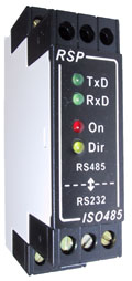
Signaling LED
TxD,RxD - switch on if log. 0 on RS232 and RS485
Dir - switch on if it is transmitting (activating RS485)
On - power supply |